555 Timer Circuit Schematic / Astable Multivibrator using 555 Timer : The 555 timer is an integrated circuit, it is extremely versatile and can be used to build lots of different circuits.
byAdmin•
0
555 Timer Circuit Schematic / Astable Multivibrator using 555 Timer : The 555 timer is an integrated circuit, it is extremely versatile and can be used to build lots of different circuits.. To observe the 555 timer in astable mode, let's build a circuit that uses the 555 timer's oscillating output to make. This tutorial provides sample circuits to set up a 555 timer in monostable, astable, and bistable modes as well wiring info: These are easy to build 555 circuits for beginners and advanced engineers. Clap switch circuit using ic 555 timer & without timer. The circuit layout is for a 555 timer in astable mode.
In this case, the fixed value of the capacitor is 100uf. Basically, this means that you will have a continuous transition from a high voltage level (determined by and slightly less than your supply voltage) to 0v at a certain frequency (number of times per second). The breadboard schematic of the above circuit is shown below. Timer b in this method acts as a voltage comparator and has no timing function. The 555 timer, designed by hans camenzind in 1971.
Schematic Circuit Diagram Astable Multivibrator using 555 ... from circuit-diagramz.com • in the time delay mode, the delay is controlled by • to understand how the capacitor is used in the 555 timer oscillator circuit, you must understand the basic charge and discharge cycles of the capacitor. The parts you add to the chip determine the final result (effect). This bistable configuration does not use any rc timing. Later it can be used in schematic editor and layout editor. Connect power and ground to pins 8 and 1 of the 555 timer (red and black wires). You can watch the following video or read the written tutorial below. Derivatives provide two (556) or four (558) timing circuits in one package. These fifteen 555 timer circuits are simple to make with widespread usability.
Timer b in this method acts as a voltage comparator and has no timing function.
Learn about the 555 timer and how it works in astable mode. This is the schematic below for the 555 timer that creates one square wave output. These fifteen 555 timer circuits are simple to make with widespread usability. Look at the circuit diagram. The standard 555 timer ic is used in a variety of timer, pulse generation and oscillator applications. Taking apart a circuit board or module and reconstructing its complete schematic is a valuable skill. One configuration of this timer creates a perfect square wave. Over 100 of 555 timer circuits and projects including the ic datasheet. The timer generates an output pulse with an on time period determined by the rc network i.e t = 1.1rc. In most cases you add a capacitor and resistor to produce a circuit known as a time delay circuit and the the 555 and 7555 are called timers or timer chips. The 555 timer ic is an integrated circuit (chip) used in a variety of timer, delay, pulse generation, and oscillator applications. Above schematic diagram shows the 555 timer monostable multivibrator circuit. A 555 timer is a very versatile.
Figure 10 shows a 555 square. The 555 timer is an integrated circuit, it is extremely versatile and can be used to build lots of different circuits. 7 below, you'll see the circuit schematic of the 555 and the parts relevant to it. • in the time delay mode, the delay is controlled by • to understand how the capacitor is used in the 555 timer oscillator circuit, you must understand the basic charge and discharge cycles of the capacitor. The 555 timer is a simple integrated circuit that can be used to make many different electronic circuits.
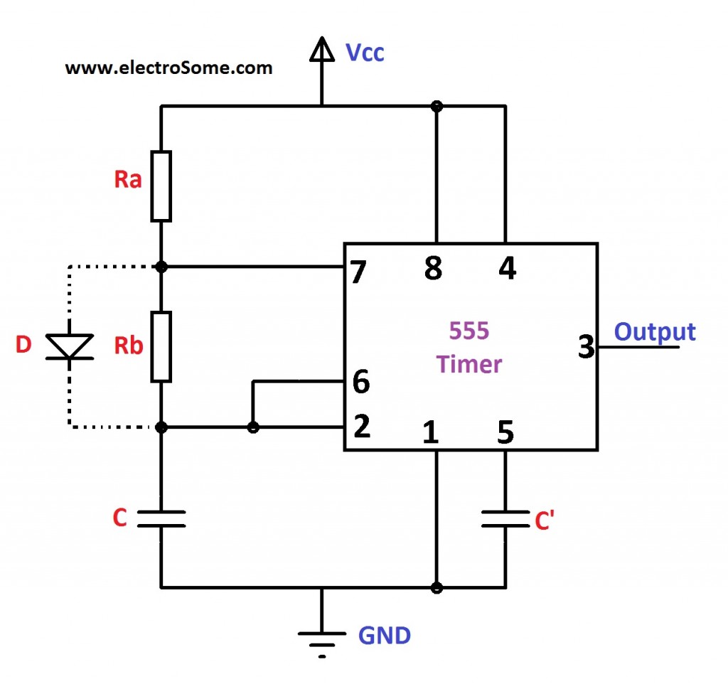
Astable Multivibrator using 555 Timer Circuit Diagram from electrosome.com In most cases you add a capacitor and resistor to produce a circuit known as a time delay circuit and the the 555 and 7555 are called timers or timer chips. The timer's internal circuitry is largely responsible for this. Connect power and ground to pins 8 and 1 of the 555 timer (red and black wires). The 555 timer can provide time delays ranging from several minutes for one cycle of operation to many thousands of cycles per second. The 555 timer ic is an integrated circuit (chip) used in a variety of timer, delay, pulse generation, and oscillator applications. These fifteen 555 timer circuits are simple to make with widespread usability. To make the same circuit as mentioned above without ic 555 timer, we will have to use the following basic electronic components and devices. The timer generates an output pulse with an on time period determined by the rc network i.e t = 1.1rc.
The breadboard schematic of the above circuit is shown below.
The 555 timer is a simple integrated circuit that can be used to make many different electronic circuits. The lm555 has a maximum typical supply voltage rating of 16v while the relay's armature coil is enabled at 12v. This tutorial provides sample circuits to set up a 555 timer in monostable, astable, and bistable modes as well wiring info: The 555 timer ic is an integrated circuit (chip) used in a variety of timer, delay, pulse generation, and oscillator applications. Figure 10 shows a 555 square. 555 ic automatically switches back to stable state after some time, this time, for which the 555 stays in quasi stable state, is determined by the time constant of rc network in the circuit. 555 timer was first introduced by signetics corporation in 1971 as se555/ne555. You can either follow the previous schematic or follow the breadboard wiring diagram below. The timer's internal circuitry is largely responsible for this. It's a simple source of oscillating in the schematic above, notice that the threshold pin and the trigger pin are connected to c1. The lm555 has a maximum typical supply voltage rating of 16v while the relay's armature coil is enabled at 12v. Si notation all the schematics in this ebook have. This bistable configuration does not use any rc timing.
Si notation all the schematics in this ebook have. A 555 timer is a very versatile. Learn about the 555 timer and how it works in astable mode. Here is the list of 40 555 timer circuits that can help you in understanding 555 timer functions.first five circuits explains. The good thing is that this chip could work directly with 12v so no driver for the mosfet is needed.
TALKING ELECTRONICS 555 Page3 from www.talkingelectronics.com This is the schematic below for the 555 timer that creates one square wave output. Look at the circuit diagram. Learn about the 555 timer and how it works in astable mode. The timer generates an output pulse with an on time period determined by the rc network i.e t = 1.1rc. In this case, the fixed value of the capacitor is 100uf. The 555 timer ic has found widespread use in a variety of applications, and is still used widely due so we will use the 10 kω resistor and two 10 μf capacitors in the timing circuit of the 555 timer. Basically, this means that you will have a continuous transition from a high voltage level (determined by and slightly less than your supply voltage) to 0v at a certain frequency (number of times per second). We can see that it us made up of 21 transistors, 4 diodes, and 15.
For standard 555 timers use timing resistor values between 1k ohms and 1m ohms.
Later it can be used in schematic editor and layout editor. We can see that it us made up of 21 transistors, 4 diodes, and 15. The parts you add to the chip determine the final result (effect). Timer b in this method acts as a voltage comparator and has no timing function. With this information you will learn how how the 555 works and will have the experience to build some of the circuits below. The timer generates an output pulse with an on time period determined by the rc network i.e t = 1.1rc. 555 ic automatically switches back to stable state after some time, this time, for which the 555 stays in quasi stable state, is determined by the time constant of rc network in the circuit. You can watch the following video or read the written tutorial below. The 555 timer is an integrated circuit, it is extremely versatile and can be used to build lots of different circuits. This 555 timer is in astable mode. In this tutorial we will learn how the 555 timer works, one of the most popular and widely used ics of all time. The good thing is that this chip could work directly with 12v so no driver for the mosfet is needed. Clap switch circuit using ic 555 timer & without timer.
Astable mode can produce digital square waveforms that go back and forth between 555 timer schematic. The timer generates an output pulse with an on time period determined by the rc network i.e t = 1.1rc.